BWRY
The document introduces how to drive the Spectra 4 small size EPDs with OTP LUT.
They include the 1.52”, 1.54”, 2.06”, 2.66”, 2.9”, 4.2” and 4.37” EPDs.
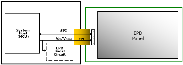
The EPDs use a single driver and that embedded T-con. The major control interface of the driver is SPI.
The host sends both the setting commands and the display image to driver through the SPI bus.
Definition of Operation Modes
The section will define the OTP memory and clarify update modes.
OTP memory
The OTP memory of the screen controller contains all the parameters to initialise the screen, as well as the waveforms for normal update. The waveforms are specific to each batch of screens and set for optimal image quality.
The host needs to read the OTP memory once, as long as it retains the values.
| Entry | Address | Value | Comment |
|---|---|---|---|
| Check Code | 0x00 | 0xa5 | Checks OTP validity |
| Layout Rev | 0x01 | Identifies the memory layout | |
| COG type | 0x02 | COG ID | |
| Vendor | 0x03 | Vendor ID | |
| Waveform Rev | 0x04 | Revision number of the waveform | |
| FPL lot name | 0x05+6 | Display FPL lot number with 6-character ASCII | |
| Colour | 0x0b | 0x04 | Supports black/white/red/yellow |
| E-ink Reserves | 0x0c+4 | ||
| COG Initial data | 0x10+32 | The data of this sector are the necessary IC initial data. |
Update modes
The screen only supports one update mode.
- Normal update will perform the complete waveform for image update. The process will go through the inverse, flashing and imaging phases. The mode will take more time, but it will bring better image performance.
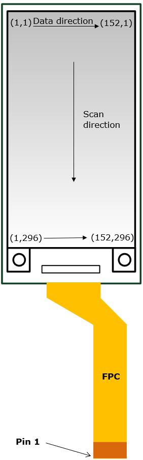
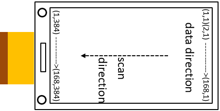
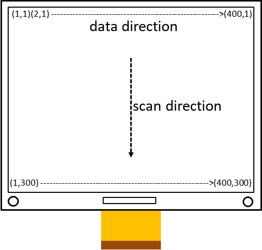
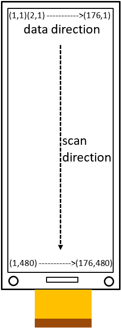
Panel Drawing
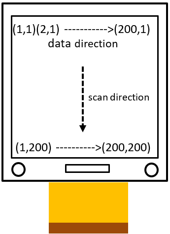
1.52"
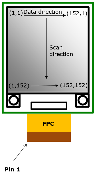
1.54"
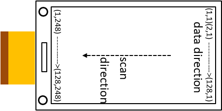
2.06"
2.66"
2.9"
4.2"
4.37"