Project Description
For this project, the following hardwares were used:
- EXT3-1 Extension board
- EXT3-1 Touch board
- 2.71” Touch EPD
- DC Motor + Stepper FeatherWing
- NodeMCU-32 v1.2
- N20 DC Motor
The remote motor control system is separated into two segments: touch panel and the motor. Each system uses the same ESP32 as controller and communication module.
Server: Touch Panel
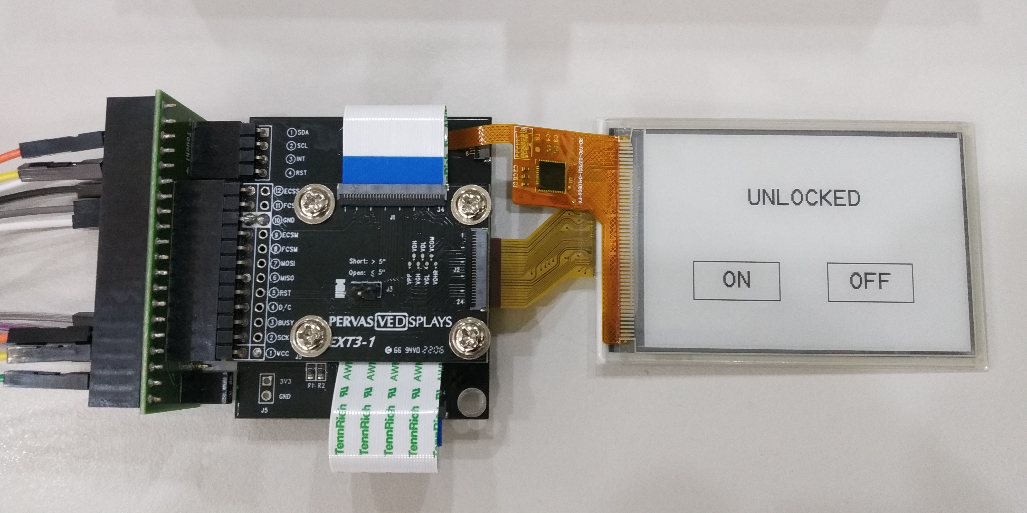
Touch-EPD assembly
Assembling the touch kit is shown in detail here.
The touch kit can be purchased through our related products page.
Info
Note that this kit does NOT include the ESP32 and the green interface board.
Connecting to the ESP32
Pin wiring to the ESP32 module is as follows:
// EPD pins
.panelBusy = 27
.panelDC = 26
.panelReset = 25
// SPI pins
.panelMOSI = 23
.panelSCK = 18
.panelCS = 32
// I2C pins
.panelSDA = 21
.panelSCL = 22
// Touch pins
.touchInt = 17
.touchReset = 16
The sample GUI shown was developed using the PDLS_EXT3_Basic_Touch. Two buttons were created to represent the ON and OFF state of a motorized lock. The demo version can be found at [].
Client: Motor Controller
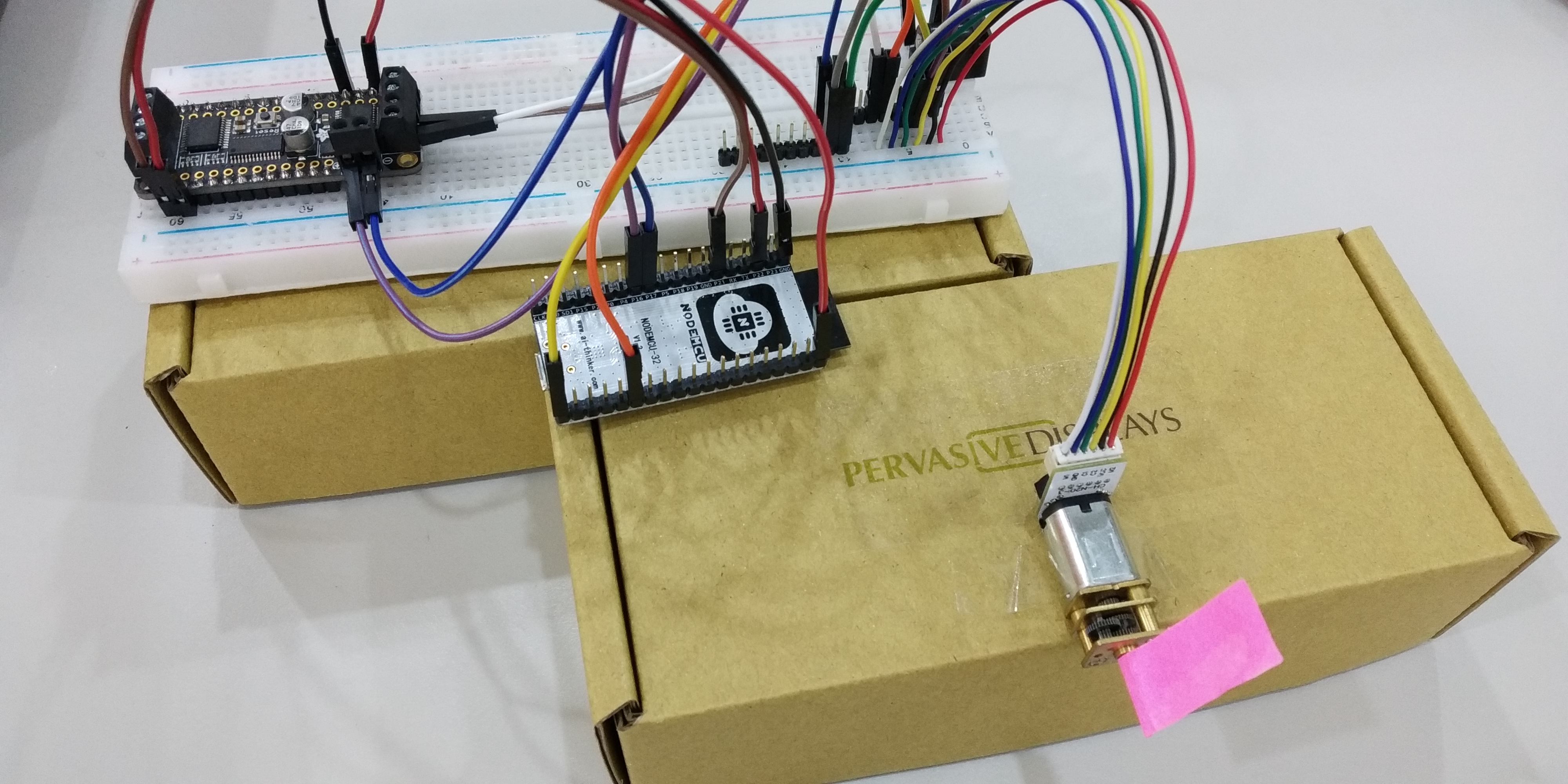
The client side is composed of the Adafruit Featherwing board, ESP32 module, and the N20 DC motor.
The Adafruit Featherwing board handles the motor driving with an I2C interfacing chip. This allows the board to handle up to 4 motors using the same number of communication pins. However, in this example, only 1 motor is used.
To ensure a closed-loop control system, a PID controller was implemented in the ESP32 module. It was adapted from [], where a transistor-based H-bridge was used. Feedback is fed into the controller through Hall-effect magnetic encoders that come together with the N20 DC motors.