Wide Large
Overview
The document introduces how to drive the e-paper displays (EPD) with the new generation driver chip.
They include the 9.7” and 12” inch.
The EPD has an internal timer controller (iTC) and uses SPI as the main control interface.
The host sends both the setting commands and the display image to the driver through the SPI bus.
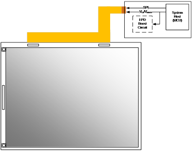
Single FPC
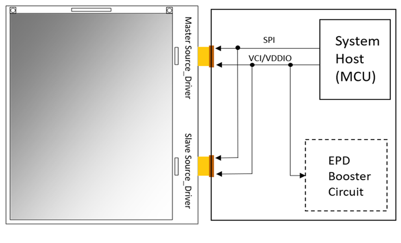
Dual FPC
Definition of Operation Modes
The section will define the OTP memory and clarify update modes.
OTP memory
The OTP memory of the screen controller contains all the parameters to initialise the screen, as well as the waveforms for normal and fast update. The waveforms are specific to each batch of screens and set for optimal image quality.
The OTP memory contains 128 bytes.
The host needs to read the OTP memory with the 0xb9 command once, as long as it retains the values.
| Entry | OTP index | Value | Comment |
|---|---|---|---|
| COG Type | 0x01 | 0x96 | Dual chip |
| Vendor | 0x02 | 0x01 | PDI |
| Waveform | 0x03 | Revision of the waveform | |
| FPL lot name | 0x04+6 | Display FPL lot number with 6-character ASCII | |
| Colour | 0x0a | 0x00 | Black/White |
| Flags | 0x1e | 0xFE | Fast update is supported. |
| Stage 1 | 0x28+8 | Stage 1 of DC/DC sequence | |
| Stage 2 | 0x30+8 | Stage 2 of DC/DC sequence | |
| Stage 3 | 0x38+8 | Stage 3 of DC/DC sequence | |
| Stage 4 | 0x40+8 | Stage 4 of DC/DC sequence |
| Address | Content | Bytes | Address | Content | Bytes |
|---|---|---|---|---|---|
| 0x00 | Reserved | 1 | 0x1B | STV_DIR | 1 |
| 0x01 | COG Type | 1 | 0x1C | MS_SYNC | 1 |
| 0x02 | Vendor | 1 | 0x1E | BVSS | 1 |
| 0x03 | Waveform Rev | 1 | 0x1E | Flags | 1 |
| 0x04–0x09 | FPL lot name (ASCII) | 6 | 0x1F | VCOM_CTRL | 1 |
| 0x0A | Color | 1 | 0x20-0x27 | Reserved | 8 |
| 0x0B | TCON | 1 | 0x28-0x2F | Stage 1 of booster boot sequence | 8 |
| 0x0C-0x0F | DRFW 0-3 | 4 | 0x30-0x37 | Stage 2 of booster boot sequence | 8 |
| 0x10 | DCTL | 1 | 0x38-0x3F | Stage 3 of booster boot sequence | 8 |
| 0x11 | VCOM | 1 | 0x40-0x47 | Stage 4 of booster boot sequence | 8 |
| 0x12-0x14 | RAM R/W Start 0-2 | 3 | 0x48-0x7F | Reserved | 56 |
| 0x15-0x1A | DUW 0-5 | 6 |
Update modes
The screen supports two update modes.
- Normal update will perform the complete waveform for image update. The process will go through the inverse, flashing and imaging phases. The mode will take more time, but it will bring better image performance.
- Fast update executes the faster waveform. COG compares the pixel data of the current image and the new image pixel by pixel, and then only drives the transition pixels. The mode can quickly complete the image update.
Panel Drawing
9.7” EPD
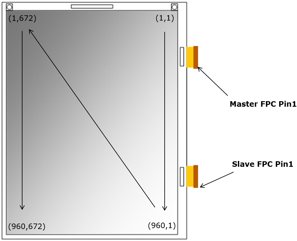
9.7"
12” EPD
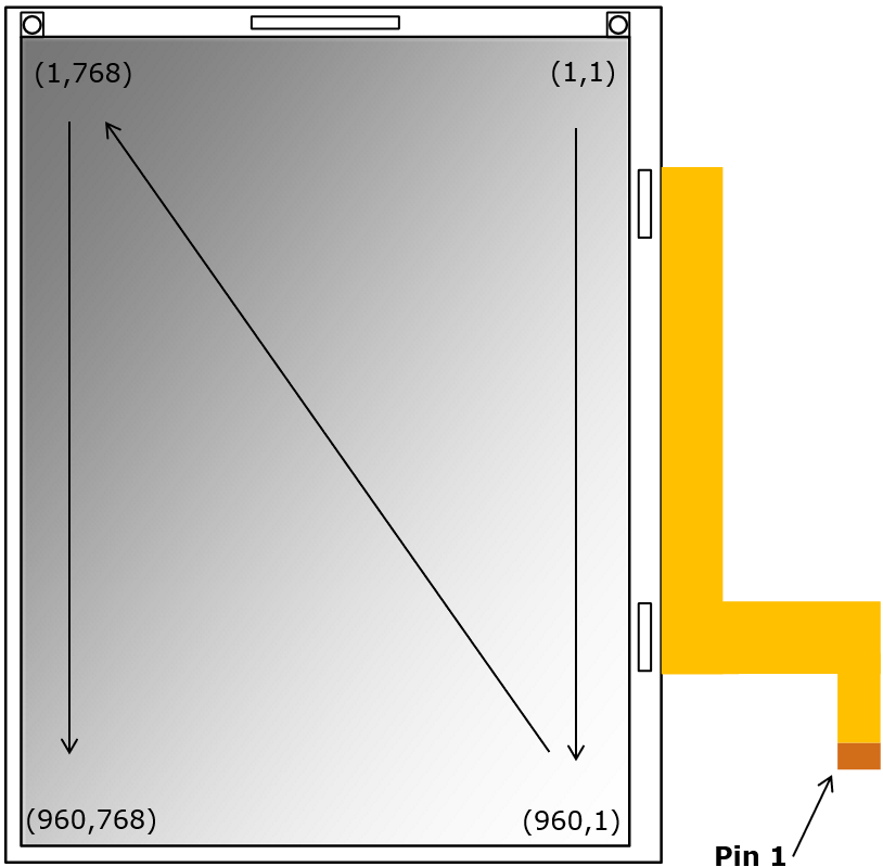
Single FPC
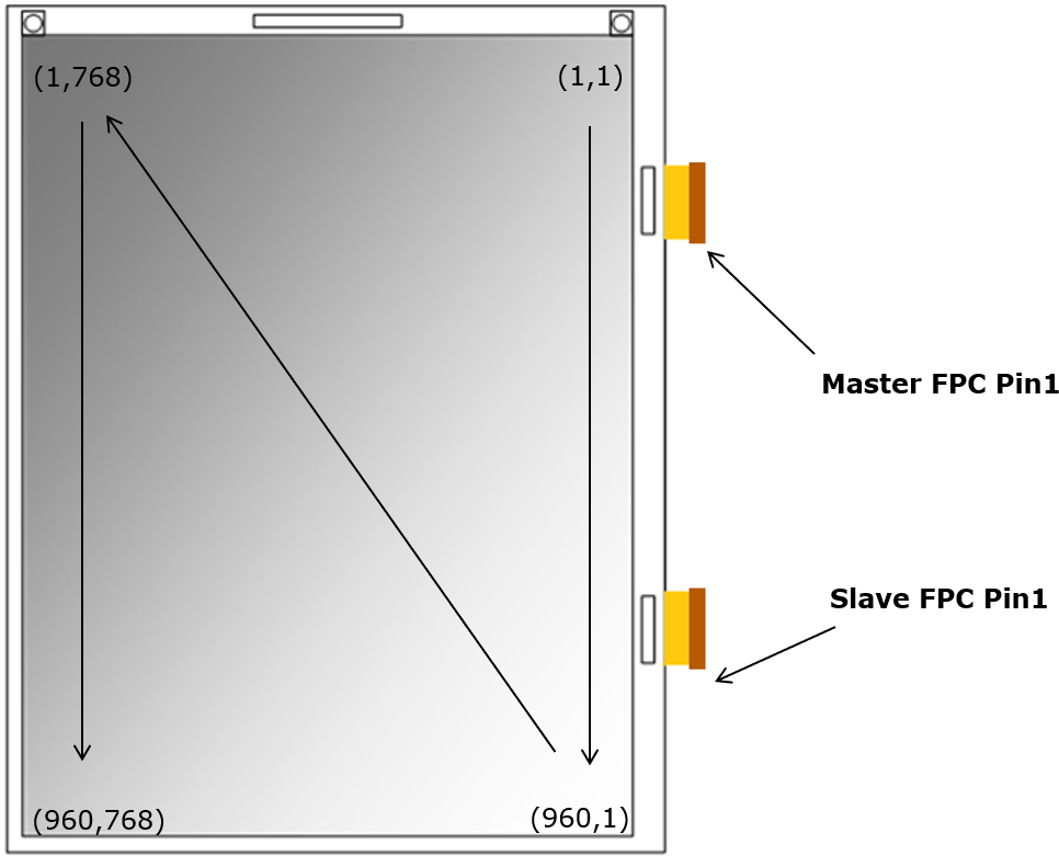
Dual FPC