Management
Fast Update Data Comparison
Fast Update needs two data buffers to store image data. One is for original (previous) image and the other is for new image. For data comparison, find the table below:
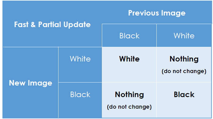
Data comparison of Fast update and Partial update
If the new data byte is the same as the previous data byte, send “Nothing” data byte. If the new data byte is different from the previous data byte, send the new data byte. Once the new image is updated on the EPD, the result image becomes the original one in order to be compared with the upcoming new image.
The key is to ask the driver to send a Nothing data byte for the targeted pixel if the existing colour will not be changed. The driver will keep the same voltage level to maintain the particles at the same pixel position.
Preparing Images
The LookUp Tables (LUTs) are arrays that store the driving parameters of timings, data bytes, colour options, cycle times and more. LUTs have been programmed in the iTC driver IC of the EPD, hence the developer only needs to send image data with very few commands to perform Fast Update.

Image data sending to iTC driver
The comparison rules have been defined in the LUTs. The developer will need to send previous and new images together with the update command to apply the Fast Update LUT to the iTC driver.
Frame Time and Stage Time
The EPD module described in this document is an active dot matrix display. It combines several sources and gates in its design. For a resolution of 200 × 96 EPD, it is composed of 96 sources and 200 gates, which means one line has 200 dots. One frame is from (1,1) to (200, 96) which is a complete screen size.
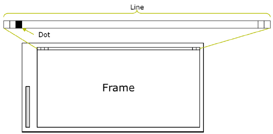
Frame, Line and Dot of an EPD
A frame time is the duration to complete one update frame and a stage time is a total duration to update the defined number of frames EPD needs the particles in ink to be driven with the targeted voltage level for multiple times to push it at the targeted position steadily. The more update frames in an update stage, the better optical performance and particles fixity.
Set the Stage Time of iTC Driver
iTC driver has defined the duration of a stage time which is programmed in the driver IC. It will continue to run the update frames according to its performance until sufficing the defined stage time. In most cases, the number of frames of iTC will be greater than that of eTC in a defined stage. Because of this, the optical performance of iTC driver is usually better than eTC driver in a fixed stage time.
To get the LUTs of Fast Update for iTC driver, you have to contact PDi and will need to sign NDA with PDi for further support.
If you would like to reduce the stage time or change the configuration of LUTs, you have to get supports from EPD vendor and understand how to set the new LUTs to send them from MCU bypass the programmed LUTs. Contact PDi if you need such support.
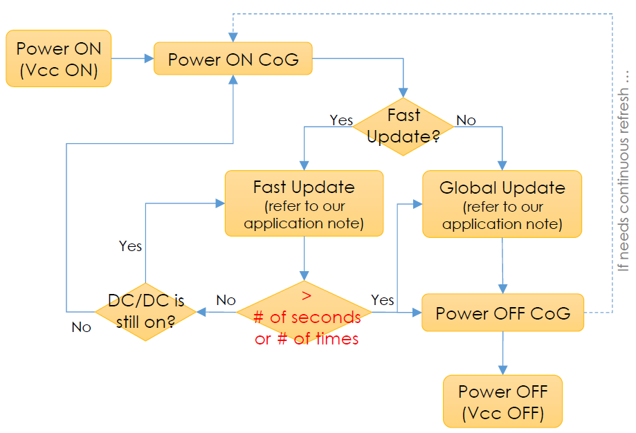
Flowchart for Fast Update
The charged particles in the ink material are in an unbalanced state while fast refreshing continuously. They need either compensation or an inverted image to clean the ghosting effect, maintain the optical performance and extend the lifetime of the EPD module. With regard to this, you have to take account of Fast Update times or whether the EPD has stopped refreshing for a period of time without any changes (the diamond shape in red below) and place a standard Global Update in good time. The figure below is the suggested EPD driving flow chart of Global and Fast Update.
Note
Per our experiments, we highly recommend that
-
after 20 Fast Updates of iTC
-
30 seconds without any screen changes (e.g. idle state)
-
ghosting effect starts to appear on screen
-
totally different template or scene you are better to run a standard Global Update or power off the CoG to wait until next cycle is coming. Item (2) depends on your use case . All the criteria also depend on your acceptance of image quality or tolerance of ghosting images
** iTC driver features shorter period of power on or off the CoG. If the duty cycle of your product is low, we would suggest you could consider power off the CoG, and then turn on the CoG p er new Fast Update to reduce the standby current. The duration of power ON + OFF CoG of iTC driver is around 100ms or less mostly.