EXT4 Board Hardware
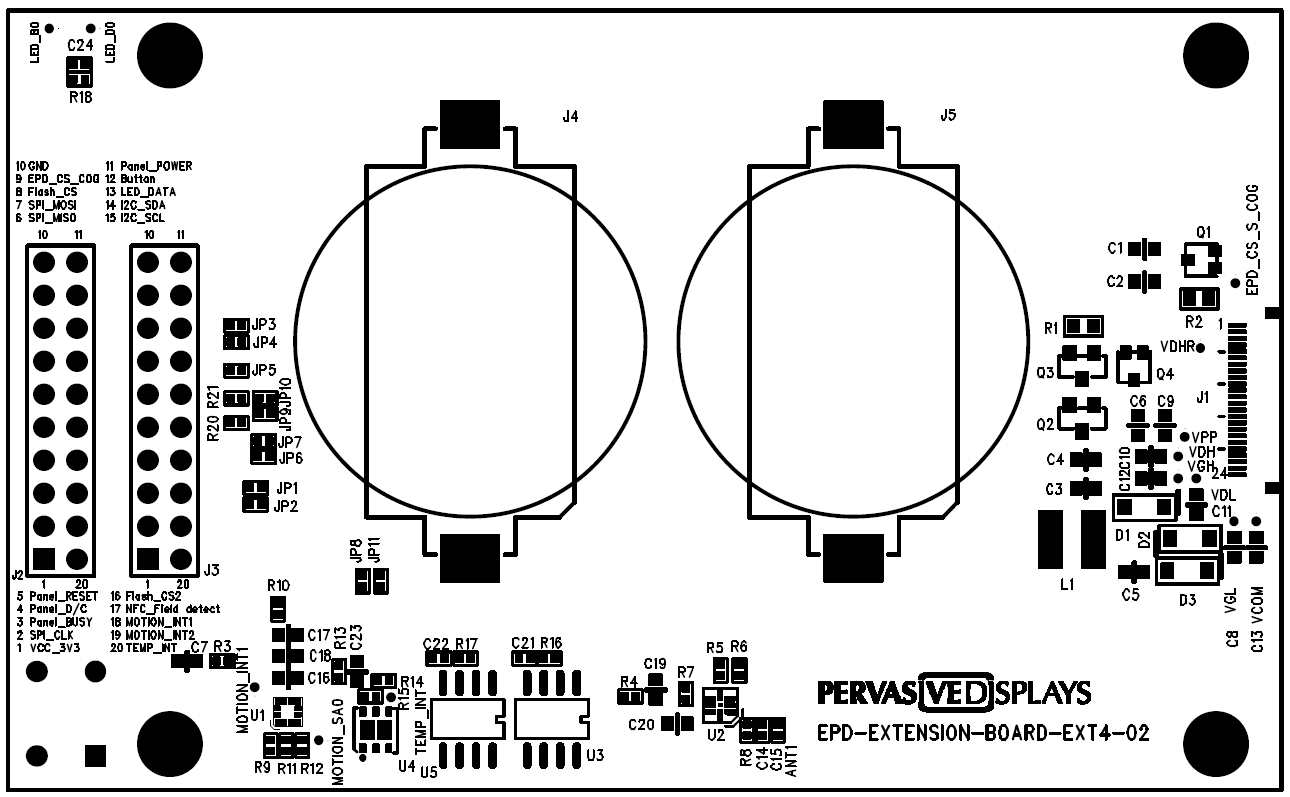
Top view
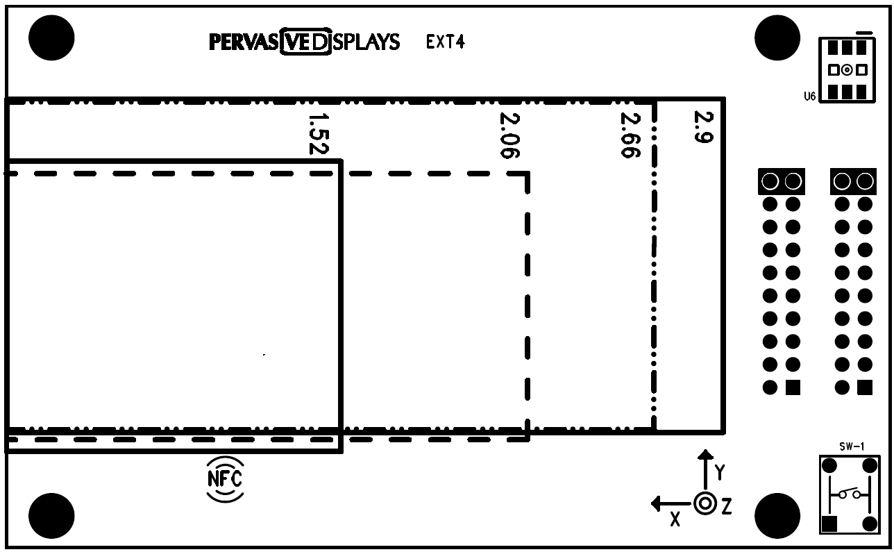
Bottom view
| Connector | Description |
|---|---|
| J1 | 24-pin connector for EPDs from 1.52” to 3.7” |
| J2 | 20-pin header for interfacing with EVK/MCU |
| J3 | Test points for measuring J2 pins |
Board Layout
EPD Extension Kit Generation 4 (EXT4 Kit) includes a 20-pin cable to quickly interface with any of your chosen development board or current design platform.
The kit has 8 Mbits of Flash memory with an allocated SOIC-8 slot for memory expansion.
Danger
When the EXT4 extension board is connected to the main controller board, ensure only one power source is used.
Either through the USB cable:
-
Remove the two CR2450 batteries
-
Power the main controller board and the EXT4 through the USB cable
Or with the two CR2450 batteries:
-
Disconnect the USB cable, and
-
Power the main controller board and the EXT4 with the two CR2450 batteries.
Peripherals
- Programmable LED
WS2813C https://wmsc.lcsc.com/wmsc/upload/file/pdf/v2/lcsc/2304060930_Worldsemi-WS2813C-2020_C5153902.pdf
- Accelerometer
LIS2DH12 https://www.st.com/en/mems-and-sensors/lis2dh12.html
- Thermometer+Hygrometer
HDC2080 https://www.ti.com/product/HDC2080
- Near Field Communication
NT3H2111 https://www.nxp.com/docs/en/data-sheet/NT3H2111_2211.pdf
Pinouts
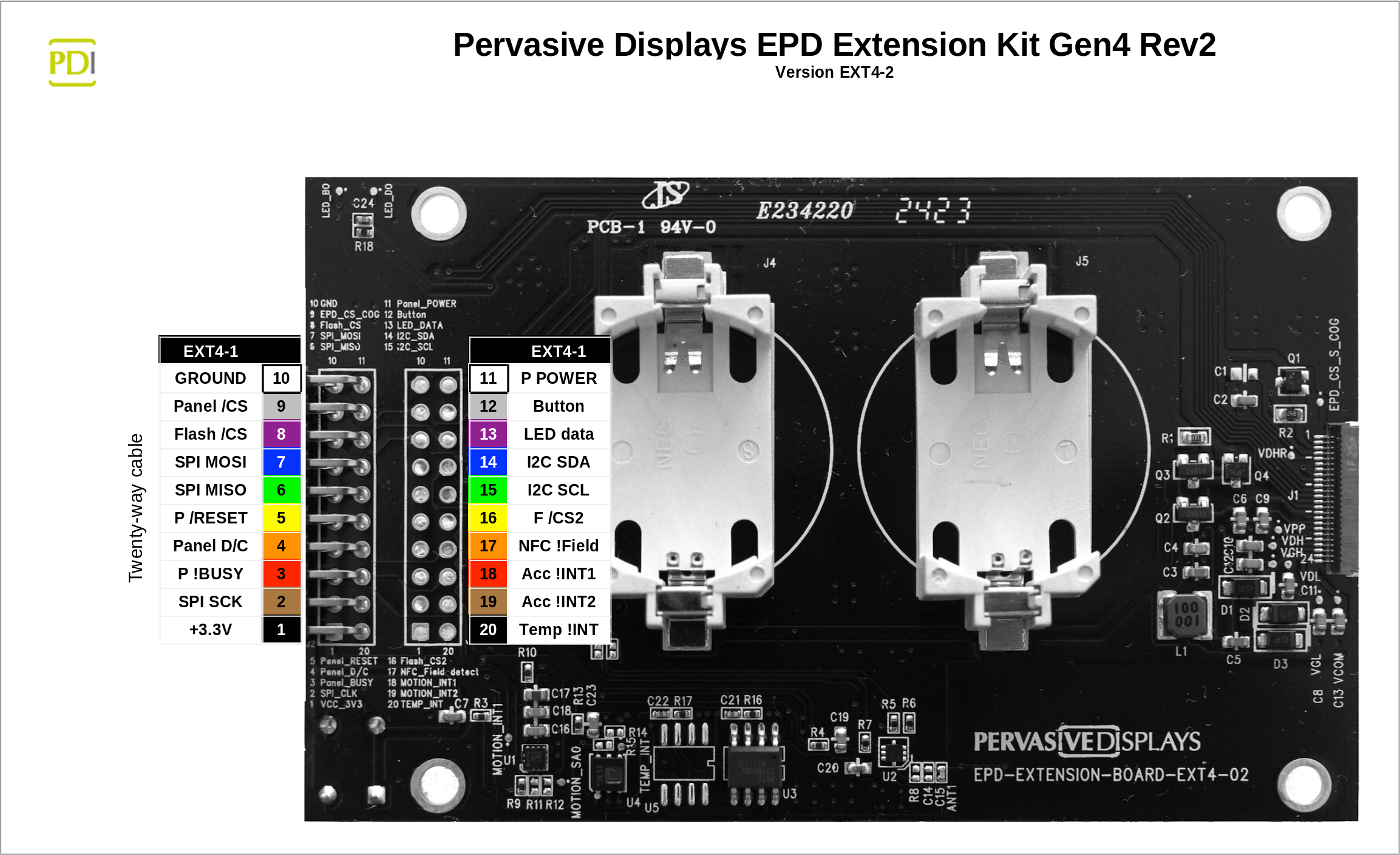
J2 Pin assignment
| Pin # | Symbol | Description |
|---|---|---|
| 1 | VCC | VCC 3.3V |
| 2 | SCK | SPI CLK, serial communication clock input |
| 3 | BUSY | Busy state output pin L: EPD driver is busy, data/command is transforming H: host side can send command or data to EPD driver |
| 4 | D/C | Serial bus for controlling data or command L: command; H: data |
| 5 | RST | Reset signal input |
| 6 | MISO | SPI MISO, serial communication data output |
| 7 | MOSI | SPI MOSI, serial communication data input |
| 8 | FCSM | Master chip select pin of Flash (U1) |
| 9 | ECSM | Master chip select pin of EPD |
| 10 | GND | Ground |
| 11 | Panel_POWER | Soft-reset circuit for EPD |
| 12 | Button | |
| 13 | LED_DATA | Input data pin for LED control |
| 14 | I2C_SDA | SDA bus |
| 15 | I2C_SCL | SCL bus |
| 16 | Flash_CS2 | Slave chip select pin of Flash (U2) |
| 17 | NFC_Field | Field detection pin for NFC |
| 18 | MOTION_INT1 | Interrupt pin 1 for accelerometer |
| 19 | MOTION_INT2 | Interrupt pin 2 for accelerometer |
| 20 | TEMP_INT | Interrupt pin for temp/humidity sensor |
Power Consumption
With all the sensors and peripherals powered, the EXT4 has a mean current draw of 1 mA during standby mode. When driving the EPD, this increases to 4 mA.
For lower power consumption, the added peripherals can be disconnected by desoldering relevant zero-ohm links.
.png)
Standby Mode (measurement between points A and B)
.png)
Driving the EPD (measurement between points A and B)
Component-level
The following table lists the individual low power/quiescent draw of each peripheral and the relevant resistor for desoldering:
| Peripheral | Current Draw | Zero ohm link |
|---|---|---|
| LIS2DH12 | 0.5μA | R10 |
| HDC2080 | 0.05μA | R13 |
| Flash | 0.007μA | R16 |
| WS2813C | 0.2mA | R18 |
| NFC | - | R4 |