Update procedure
COG Power On
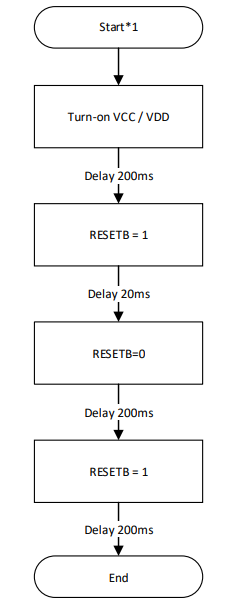
Initial states
- VCC/VDD = 0
- RESETB = 0
- CSB = 0
- SDA = 0
- SCL = 0
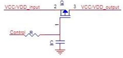
Danger
In order to avoid current surge, it is recommended to include a soft-start when VCC/VDD is activated.
COG Initialize
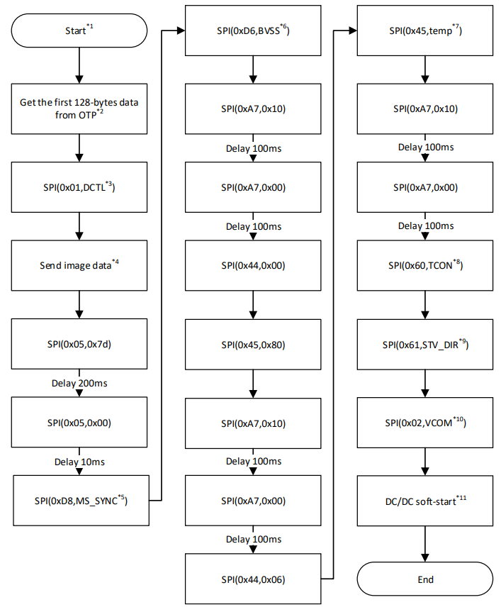
Comments
- Item 2 See Read OTP Data
- Item 4 See Send Image to EPD
- Item 7 See Temperature Setup below
- Item 11 See DC-DC Soft Start
Temperature Setup
The acceptable temperature range is -40 to 87 deg Celsius, with 0.5 deg C per step resolution.
For example:
| Value (deg C) | HEX |
|---|---|
| -40 | 0x00 |
| 0 | 0x50 |
| 25 | 0x82 |
| 87 | 0xFE |
The following data values are read from
| Data | Register Address - OTP Memory | |
|---|---|---|
| DCTL | 0x10 | |
| MS_SYNC | 0x1C | |
| BVSS | 0x1D | |
| TCON | 0x0B | |
| STV_DIR | 0x1B | |
| VCOM | 0x11 |
Send Image to EPD
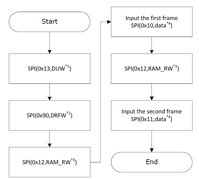
Comments
| Register | Value |
|---|---|
| DUW | 0x15 to 0x1A |
| DRFW | 0x0C to 0x0F |
| RAM_RW | 0x12 to 0x14 |
Info
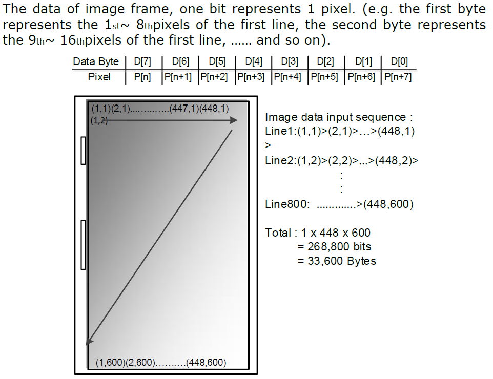
Item 4: Data size of 33,600 bytes
Image Format
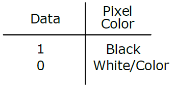
- First Frame
The frame is the “black” frame. The data “1” represents the black color pixel and data “0” represents both white and color pixel.
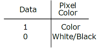
- Second Frame
The frame is the “Color” frame. The data “1” represents the color pixel and data “0” represents both black and white pixel.
DC/DC soft-start
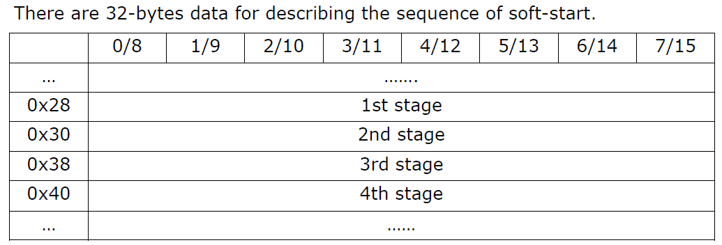
The sequence totally has 4 stages. Each stage has 8-byte parameters. The bytes of each stage can be interpreted in 2 ways.
Data structure and definition
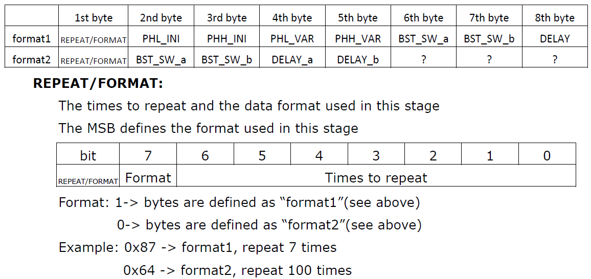
- PHL_INI
Define the initial value of PHL (the first data of the register 0x51)
- PHH_INI
Define the initial value of PHH (the second data of the register 0x51)
- PHL_VAR
The byte represents the changing value of PHL with each iteration (REPEAT)
- PHH_VAR
The byte represents the changing value of PHH with each iteration (REPEAT)
- BST-SW-a
BST_SW setting is the power on/off manager (Reg 0x09) at the start of the phase
- BST-SW-b
BST_SW setting is the power on/off manager (Reg 0x09) at the start of the phase
Both PHL_VAR_n and PHH_VAR_n could be a negative number. The negative number is represented by 2’s complement. Example: -5 equals 0xFB
- DELAY
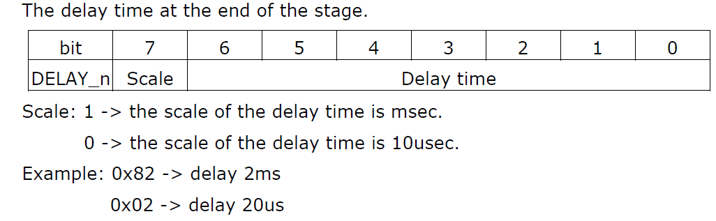
- DELAY_a
Same as “DELAY” but inserted after BST-SW-a
- DELAY_b
Same as “DELAY” but inserted after BST-SW-b
Flowchart
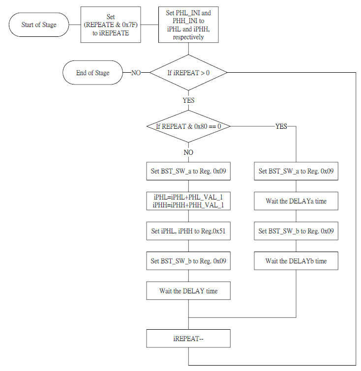
Info
Note: iREPEAT, iPHH, iPHL are variable
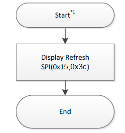
Update Command
Turn off DC/DC
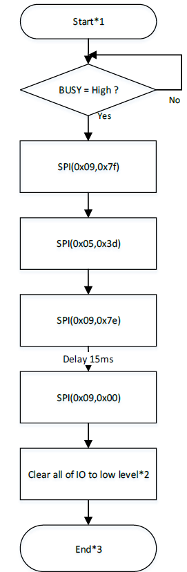
Warning
VCC/VDD, RESETB, A0, CSB, SCK, MOSI should all be LOW before END.